Using Lifecycle Definition Designer
Lifecycle Definition Designer allows you to use a diagram-based interface to assign tasks to a workflow definition, and set up the process flow of tasks included in the workflow definition.
Note You must set up tasks in Lifecycle Task Maintenance before you can add the tasks to a workflow definition diagram.
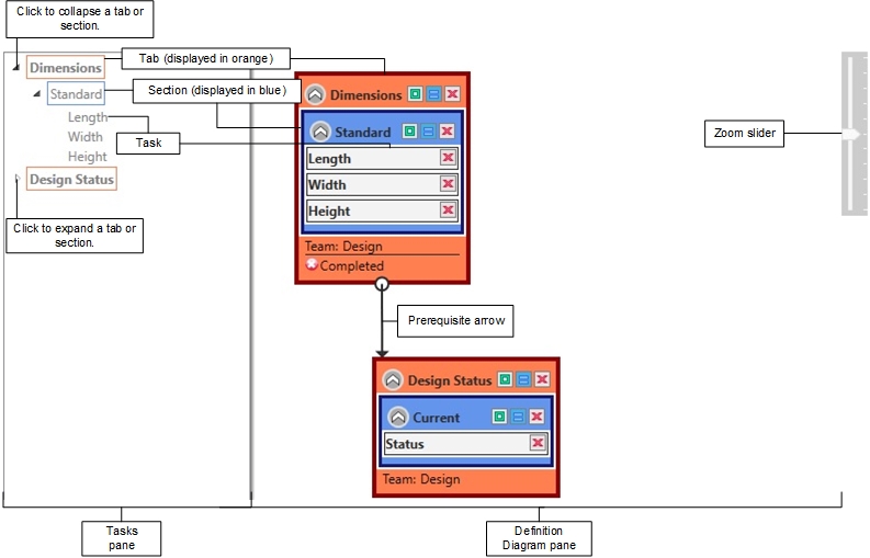
The Lifecycle Definition Designer window appears as follows:
Setting Up Workflow Definition Diagrams
To set up a diagram for a workflow definition:
-
Drag a tab, section, or task from the Tasks pane to the Definition Diagram pane. In the Tasks pane, the tab, section, or task name appears in gray to indicate it is used in the diagram. In the Definition Diagram pane, a Tab, Section, or Task box appears to represent the tab, section, or task. If you drag a tab or section, the tasks and/or sections it contains are automatically moved to the Definition Diagram pane.
-
If you want to change the default team for a tab, section, or task, right-click the Tab, Section, or Task box in the Definition Diagram pane, select Assign Team, and then select the team that should be assigned to the tab, section, or task. If you want the team to be assigned by team rules set up in Lifecycle Rule Maintenance, select Rule Based.
Note If you select a team and also set up team rules, the team rules are ignored. For more information on team assignment, see Product Lifecycle Management FAQ.
-
If the tab, section, or task must be in a specific status before an alert is sent to users to indicate they should perform data entry for another tab, section, or task, right-click the tab, section, or task, select Add Status, and select the status.
Example If you want users to be alerted to perform Task B only after Task A is completed, select the Completed status for Task A.
Select Any if an alert is sent when the status is any of the other statuses.
NOTE A tab or section's status is Completed when all included tasks that cannot be skipped are completed or cancelled.
-
Repeat step 3 for all statuses that you want to trigger alerts. If you want to remove a status, click the
 button to the left of a status name.
 -
If a tab, section, or task can be skipped, right-click the Task box for it, and select May Skip. The Tab, Section, or Task box appears in gray to indicate it can be skipped.
-
Repeat steps 1-5 until all tabs, sections, and tasks for the workflow definition appear in the Definition Diagram pane. If you run out of space, you can zoom out to increase the available space. For more information, see Zooming In and Out below. If your definition diagram requires more space than is visible, you can click the white space in the Definition Diagram pane and drag in any direction to scroll to a blank area of the pane. You can then add or move boxes into this area.
-
Drag each status to the tab, section, or task that occurs later in the process. A prerequisite arrow appears to indicate the link between the tabs, sections, and/or tasks.
-
For each prerequisite arrow, right-click the starting point (
 ), and set up the prior task options to indicate if a tab, section, or task is a prerequisite or required and the number of days between the tabs, sections, and/or tasks. Arrows are color coded to provide you with additional information. Prerequisite arrows appear green and prerequisite arrows that are required appear purple. For more information on prerequisite arrow settings, see Prerequisite Arrow Settings below.
 -
Arrange the workflow definition diagram so you can clearly see the process flow between tabs, sections, and tasks. For more information, see Arranging the Definition Diagram below. You can use the Designer toolbar to help you arrange the diagram. For more information, see Using the Designer Toolbar below.
-
Click the OK button in the ribbon to save the workflow definition diagram.
Zooming In and Out
You can drag the Zoom slider (below) up and down to zoom in and out of the Definition Diagram pane.
![]()
If you drag the slider to the top, the diagram displays at twice the default size, and if you drag the slider to the bottom, the diagram displays at half the default size.
You can also zoom in and out using the scroll wheel on your mouse (if your mouse includes a scroll wheel).
Using the Designer Toolbar
The Designer toolbar appears at the top-right of Tab, Section, and Task boxes, and appears as follows:
![]()
The following table summarizes how to use the buttons in the toolbar.
|
Button |
Description |
|
|
Click this button to change the size of a Tab or Section box to use the least amount of space to display its contents. Note This button is not available for Task boxes. |
|
|
Click this button to enable or disable Simplified mode for a Tab or Section box. The button remains depressed when Simplified mode is enabled. When you enable Simplified mode, the following occurs:
Note This button is not available for Task boxes. |
|
|
Click this button to delete the Tab, Section, or Task box. You can add the box back to the diagram by dragging it from the Tasks pane again. |
Arranging the Definition Diagram
You can drag Tab, Section, and Task boxes in the Definition Diagram pane until the boxes accurately convey the process flow of your workflow definition. When you drag a box that is linked to another box, the prerequisite arrow automatically moves to best display the link.
When you click an arrow or box, it appears red to indicate it is selected. You can press the Delete key to delete a selected box or arrow.
As you drag tabs, sections, and tasks, keep the following rules in mind:
-
You can drag tabs anywhere in the Definition Diagram pane, but you cannot drag tabs into other tabs, sections, or tasks.
-
You can only drag a section into a tab.
-
You can only drag a task into a section or tab.
If you want a Tab or Section box to take up less space in the diagram, click the ![]() button at the top-left of the box. When you click this button, the tasks and/or sections contained in the box are hidden. Use this feature to temporarily hide complex boxes that you have set up and do not need to view. If you click the
button at the top-left of the box. When you click this button, the tasks and/or sections contained in the box are hidden. Use this feature to temporarily hide complex boxes that you have set up and do not need to view. If you click the ![]() button in the Designer toolbar before you click the
button in the Designer toolbar before you click the ![]() button, the box will also use the least amount of horizontal space. You can click the
button, the box will also use the least amount of horizontal space. You can click the ![]() button at the top-left of a box if you want to redisplay the contents of the box.
button at the top-left of a box if you want to redisplay the contents of the box.
Prerequisite Arrow Settings
You can right-click a prerequisite arrow to change link settings. The following options are available:
|
Button |
Description |
|
Prerequisite |
Select this option if a tab, section, or task is a prerequisite for a linked tab, section, or task. If you select this option, a task assignment alert is not sent for a task until the prerequisite tab, section, or task is completed. Usually, prerequisite tasks are also marked as required tasks unless used in a repeated loop (see example below). |
|
Required |
Select this option if a tab, section, or task is required to be completed before a linked tab, section, or task is completed. If you select this option, assigned users can still enter data, they simply cannot complete the task until the required tab, section, or task is completed. |
|
Days After |
Enter the number of days after a tab, section, or task that the linked tab, section, or task occurs. |
|
Date Dependency Days |
Enter the number of days after a date task that determines the date for a linked date task. Use this feature when one date is dependent on the value of another date. Example Task A and Task B are linked date tasks in a workflow definition, and you enter 5 as the date dependency days. If a user enters 1/1/2020 during data entry for a workflow that uses the workflow definition, data for Task B is automatically entered as 1/6/2020. Dependent date tasks are not automatically marked as completed. |
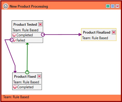
Example of Using Prerequisite and Required Tasks
A workflow definition has a task called Product Tested, which is a check box that is selected when a new product has been successfully tested by the Quality Assurance team. If the status of the Product Tested task is Completed, the Product Finalized task is performed. If the status is Failed, the Product Fixed task is performed. After the Product Fixed task is performed, the Product Tested task is performed again. In this situation, all the related tasks should be set up as prerequisites. The tasks also should be set up as required tasks except for the Product Fixed task. The Product Fixed task may not be performed at all, so there is no need to make it required before performing the Product Tested task. The following workflow definition diagram illustrates this example.